How To Write Small and Do Other Things Small Part 2: Avoiding the EUV Catastrophe
Published:
by:
Moshe Dolejsi
Estimated reading time: ~10 minutes
So, we previously talk a bit about immersion, and low K tricks to get 193 nm wavelength light down to 82 nm pitch features. This is the state of the art 193 immersion (193i) photolithography using an ArF laser. But hold on a second we know that Intel’s 10 nm node has a 34 nm fin pitch and a 36 nm metal pitch. How is that possible?
Today we are going to talk about density multiplication. Density multiplication is a family of processes that allow you to take a given pitch of features (say 82 nm) and subdivide that pitch into equal parts. We often say we are achieving 2x, 3x or 4x density multiplication (41 nm, 28 nm, and 21 nm respectively if we start at 82 nm). Before we get into the different techniques here is a table that roughly describes how the number of process steps required scales with the density multiplication you achieve (N).
| Process | Pros | Cons | Process Step Scaling |
| EUV Lithography | Minimal Extra Steps | See Previous Article $ $ $ $ $ |
Litho: 1-2 Dep: 1 Etch: 1 |
| Self-Aligned Multiple Patterning (SADP, SAQP, SAOP) | Self-Aligned | Pitch Walking Mainly 1D layout |
Litho: 1 + (cuts) Dep: Etch: |
| Litho-Etch Litho-Etch (LELE, LE2, LELELE...) | 2D layout | Overlay is Tricky | Litho: Dep: Etch: |
| Directed Self-Assembly | Minimal Steps $Cheap$ Thermodynamically Guaranteed CD/Pitch |
Defects (~0.5/cm2) CD/Pitch is Material Specific |
Litho: 1 + (cuts) Dep: 1 Etch: 1 |
Self-Aligned Multiple Patterning
For a more in depth look at EUV you can read the Previous article, so let’s start with Self-Aligned Multiple Patterning (SAMP). I’ve created an example flow below, please note that there are many different materials that can be used for these flows.
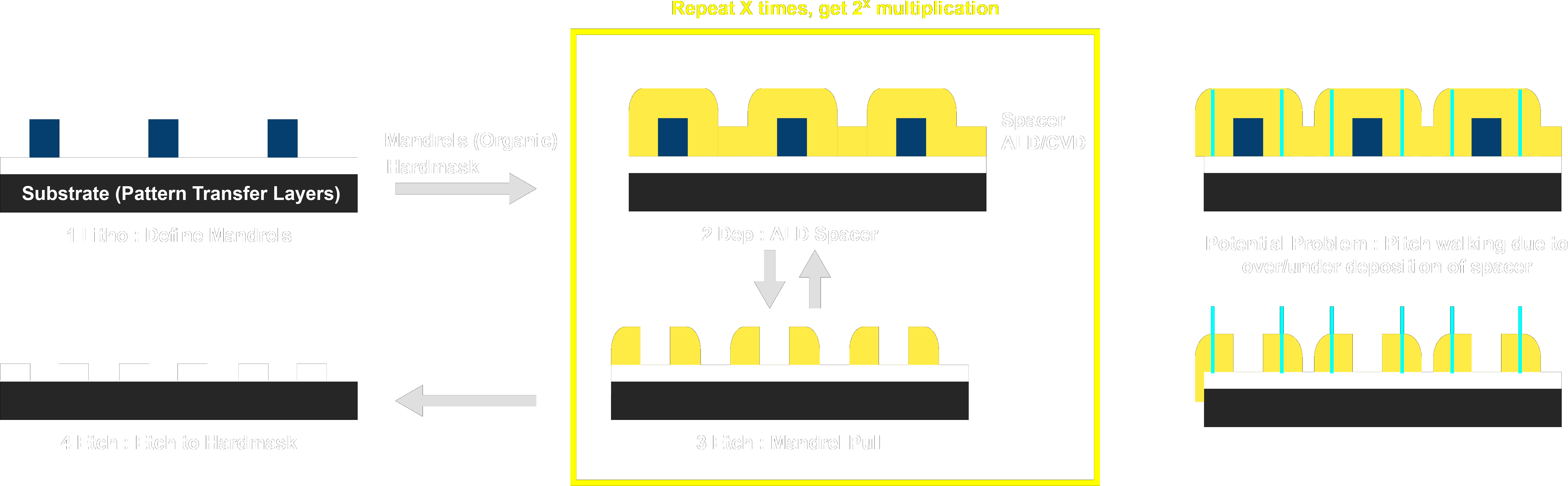
To begin with we create a lithographically defined pattern. This pattern is called the mandrel, which is a loan word from machining that describes something you bend other materials over. From here you conformally deposit a spacer material through either Atomic Layer Deposition (ALD) or Chemical Vapor Deposition (CVD). You’ll notice at this step that due to the conformal nature of the deposition the material is approximately twice as thick directly to the left and right of the mandrel. An anisotropic etch, (straight down), will etch the thickness of the spacer, leaving spacer material only where it was doubled up on the side of the mandrels. This etch can be tuned to also remove, or ‘pull’ the mandrel at the same time. After the conformal deposition and subsequent mandrel pull you have doubled the density. This process can be repeated 2x or 3x with different materials and etch chemistries to quadruple or octuple the density. After you have as many spacers as you want, you etch these spacers into the hard mask and from there into whatever active layer you may have underneath.
The most important thing about multiple patterning is that it is a self-aligned strategy. That is to say once you have lithographically defined your first set of mandrels, all the further features you create are guaranteed to be aligned to those mandrels. This is in contrast to other multiple exposure techniques where you need to be sure when you unload and reload the wafer that the wafer is exactly where it was before to get things to line up. Self-Aligned techniques deal with this so called ‘overlay error’.
The tradeoff is that while you are no longer dependent on overlay error in your stepper, you are now very dependent on your deposition and etch tools. The spacers become your new patterned lines. That means the center of the spacer defines the center of the line, or placement error. What defines the center of the spacer? Well that would be the width of the spacer after the mandrel pull. As you can see in my schematic if you make the spacers a bit too wide you will shrink one set of pitches and expand another set of pitches. The situation just becomes worse as you repeat the process for Self-Aligned Quadruple Patterning (SAQP) or even Self-Aligned Octuple Patterning (SAOP). Because of the way the pitches walk away from each other, this is called pitch walking.
Another less minor issue is that because SAMP makes spacers through conformal deposition it results in concentric rings around the mandrels. These rings need to be cut or parts of them blocked to get functional devices. This means you may need to use multiple subsequent exposure to make these cuts. These block/cut masks can be at much bigger pitch though, but do still pose an additional expense. These masks are why Brian Krzanich said that Intel’s SAQP required 5 or 6 exposures. I won’t go into this in too much detail here, but a big part of placing cuts and blocks is resolving color conflicts. Maybe we can talk about design rules a bit later, but for now just remember that the more regular features are the easier they are to pattern with SAMP. Fins for finfets are very regularly spaced, and you only need to cut to separate the fins between transistors which makes SAMP a great choice for fins.
Summary: SAMP is great for very regular features, like fins, reduces overlay (lithographic) error, but requires tight deposition control to avoid pitch walking which causes placement error. SAMP also requires cut and blocking masks to make relevant features.
Litho-Etch-Litho-Etch
Now let’s take a look at Litho Etch Litho Etch (LELE or LE2). Litho Etch is a great alternative to SAMP because it allows you more freedom with where you place everything. Non-concentric features are no longer a problem. It also doesn’t require cut or blocking masks because you pattern each set of features on its own mask anyways. Samsung has almost exclusively been using LELE for pitch multiplication and is currently using LELELELE (4X) routinely. (except for fins where they use SAMP).
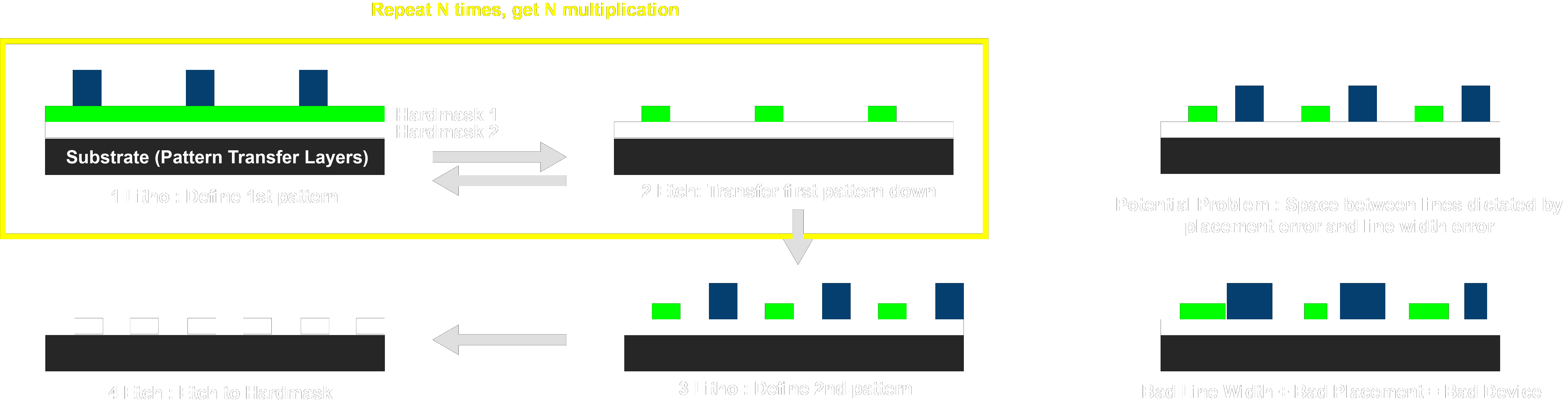
The flow here is pretty straight forward. You essentially need a mask material for each lithography you are doing. You pattern one set of features and then move over a very precise amount and pattern a new set of features. Because you are using multiple masks in the process it can very easy to simply make sure each mask only has features that are 82 nm apart. This allows you to just do your exposure and not have to worry about cutting or blocking masks later. Unlike SAMP which relies on pitch doubling, each repetition of litho etch gives you a single additional multiplication ie 4x density multiplication requires you to dep and etch twice with SAQP but requires a full four litho-etch steps.
Here the drawback becomes the overlay precision of your tool. Luckily modern 193i tools are quite good, with 3 times the standard deviation (3σ) of overlay being under 1.5 nm, but once you add on the variation in line width (LWR) it’s easy to see how LE4 can start to get difficult.
Summary: Come on it’s really short.
Directed Self-Assembly
First, let me state my bias by saying I am a PhD. candidate in Dr. Nealey’s group at the University of Chicago researching Directed Self-Assembly or DSA.
Definitely the odd man out of the group, Directed Self-Assembly, is closer to SAMP than you might guess. DSA, like SAMP, is inherently a self-aligned strategy that creates regularly alternating features aligned with lithographically defined template. Simply put, in DSA we take a bunch of democrats and republicans and handcuff them together. We a bunch of these pairs into a room and let them mingle. At the end of the day we open the door and find that all the republicans are clustered up, and so are all the democrats because they don’t want to talk to each other. This as you can imagine is a bit of a mess so we use a trick. We put down a line of TV’s tuned to Fox news (or MSNBC) periodically throughout the room, this directs the clusters to be very well ordered.
 |
 |
| Click or Tap to enlarge | |
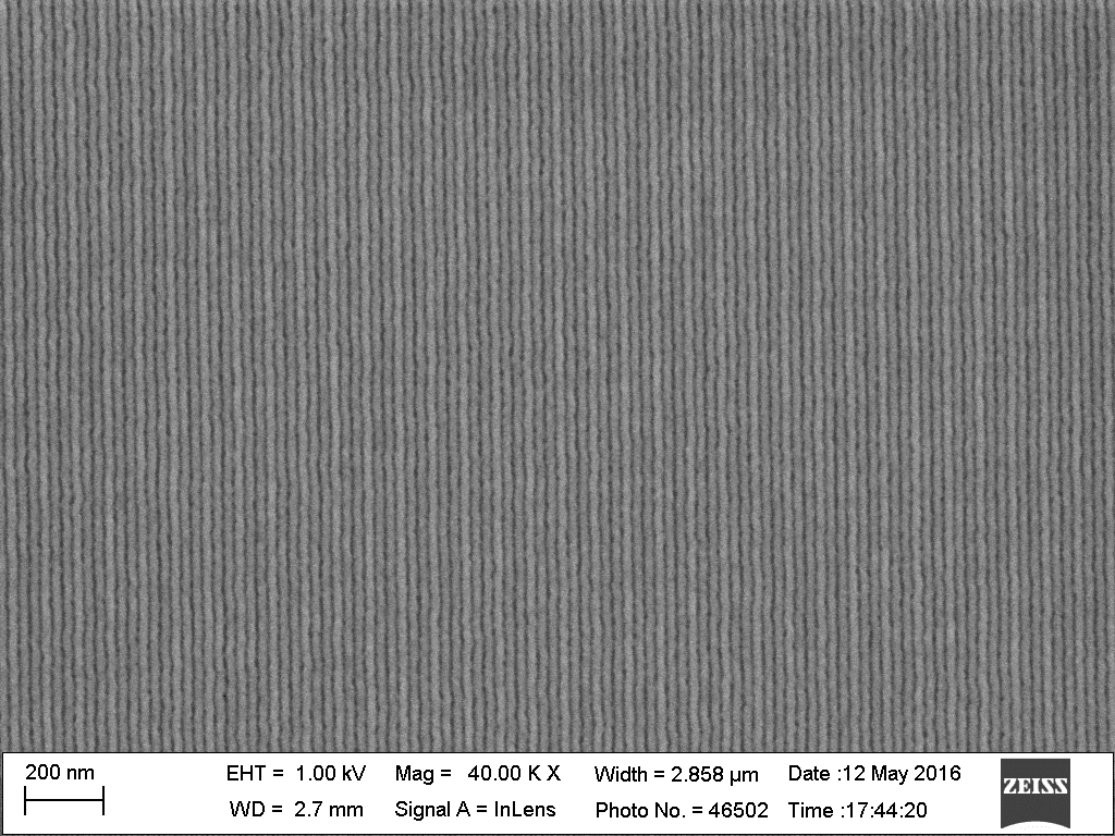
To make it a bit clearer here is a photo of self-assembled, and directed self-assembled samples from some of our recent papers. 1 2
In DSA, we use materials called block copolymers (aka handcuffed pairs) that self-assemble into regular features. The features formed depends on the relative size of the blocks in the pair (1 democrat and 3 republicans, maybe you get circley spots, but if the ratio is roughly equal you get lines), and more importantly the amount that the pair hate each other which we call Chi (χ). If the two blocks don’t hate each other enough they won’t separate, and the smaller features you want the more they need to hate each other. Thermodynamics, the laws of the universe, take all these things into account and determines the exact size, and type of features that will be formed. This means that by selecting a proper material you can ensure an exact pitch every time.
Let’s look at the DSA LiNe flow that our group is known for.
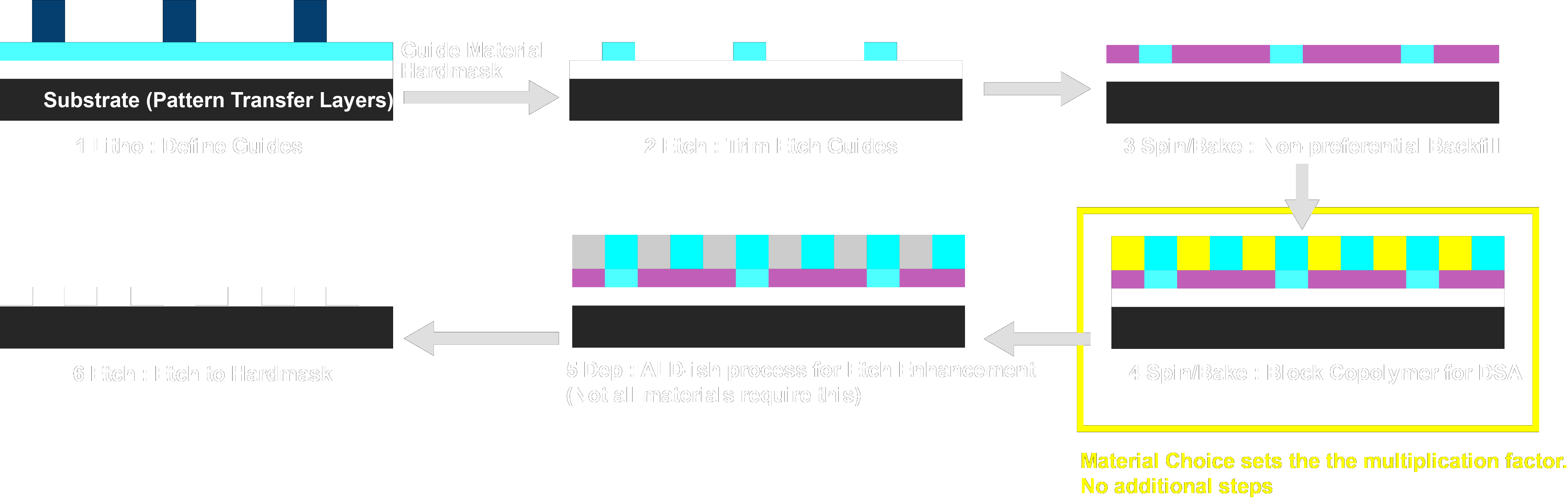
We start with a guide material on our substrate. This material is designed to strongly interact with one of our blocks. We use standard lithography on the track (or e-beam lithography in the lab) to define guidestripes, that we then each into the guide material. These guides are often made of the exact same molecule as one of the blocks so that we can maximize any potential interaction with that block. Afterwards we spincoat a backfill material. This backfill material is specifically tuned to interact equally with each block, to help shield any effects of the substrate. Then we spin coat our block copolymer, which has a specific pitch that is half, third, or a fourth etc of the starting pitch. Multiplication of up to 10x has been demonstrated by our group previously, with pitches down to 16 nm. An anneal is then performed to let the polymer assemble, afterwards an ALD like process can be performed to convert a block to aluminum oxide for better pattern transfer, or the polymer pattern can be directly transferred.
As you can imagine this process can be incredibly cheap. Aside from the initial lithography, you need an additional etch to make guides, and maybe an extra deposition to enhance the final etching, but all other steps just need a hotplate, or a spin coater neither of which are particularly expensive. On top of that thermodynamics insures a precise pitch is achieved every time, with a precise line width, which is why DSA is potentially useful for increasing uniformity.
So what are the problems? First of all DSA is very material heavy. You need to synthesize a minimum of three materials, a guide, a non-preferential backfill, and the block copolymer itself. There are numerous constraints on exactly which materials can be used, although poly(styrene-block-methyl methacrylate) (PS-b-PMMA) is very well studied by now, and is capable of achieving 25 nm+ pitches quite readily, and there is active development into new systems that can go much smaller.
The main problem though is defects, You can imagine that the random mixture of dems and reps takes quite a bit of jostling to straighten out into perfect lines. It might be that once in a billion or trillion times a dem might find himself surrounded by a number of republicans and can’t get to his buddies to form a nice line. This causes a defect in the assembled structure. Su-mi 3 did some great simulations that show the assembly process and you can see how during the formation of line features the polymer needs to bridge across. 4
Video reference - 4
Lots of work has gone into altering process parameters to push defectivity down, but the last public number I saw was 0.57 defects per square centimeter, which is still an order of magnitude or two too high.
Summary : DSA is cheap, but very material dependent, and defectivity can be difficult to control.
As you can see there is currently no right answer for every layer for every fab, but there are lots of choices available and lots of research into new solutions are in the works.
Read the previous articles in this series:

Smart Guy & Technical Writer
PhD Candidate studying nanofabrication at University of Chicago